Sunday, November 29, 2009
Final Requirements
Your final CD should contain:
2 jpegs or PDFs of the boards.
1 AutoCad file
1 Rhino file
Make sure the CD has your name and PID writen clearly on the CD- Please no jewel boxes.
The final is due December 7th by 6:45 pm.
I will not except any late projects.
Thursday, October 15, 2009
Grades...
These grades are for the completion of the autocad drawings as of 10/26/09.
2653655 B+
2675210 C-
2234955 A
3011585 C+
2060221 B++
1772324 A
2359651 B-
2667572 C+
3012729 B+
2191262 A-
1020238 F
2675953 A
1665839 C+
2662135 A
1730249 B+
2873737 B-
1665252 F
1647875 A-
1682667 B
2638682 A-
2673816 C+
2340251 A-
2192830 F
1936964 A-
2284379 F
2640520 F
2284387 C
1674813 B++
2132399 F
2642119 B+
2642240 A-
1735755 C+
2105746 C+
2645121 C
2380166 C
3012785 B
3008345 C+
2330690 B
2309105 A
3017565 F
1665869 F
2668018 F
2584954 C
1351526 A
1669087 A
2191362 F
2391573 F
3013971 A
2635750 B+
2650524 D
2393914 F
Monday, September 14, 2009
Tuesday, September 1, 2009
Layer Names
Girls and Guys,
Some of you requested a list of the layers and their details for class.
Here is a list of the layers.
Name of Layer - Color - Type - Lineweight
1.) BASELINE - RED - continuous - Default
2.) CUTLINE - BLUE - continuous - .40
3.) THINLINE - YELLOW - continuous - .05
4.) DASHLINE - GREEN - dotted line - .09
5.) COLUMN GRID - CYAN - continuous - .09
6.) WORKING GRID - random - continuous - default
7.) WORKING LINE - random - continuous - default
Email me if there are any questions.
_Andrew
Monday, August 31, 2009
Exercise 2
Make a new layer, use a color you haven’t used yet, a very thin line weight, and load a new dashed line. Call the new layer grid
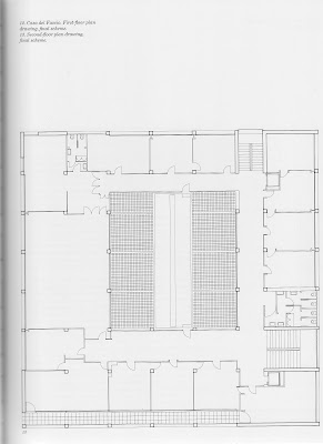
The Casa del Fascio works on a 15-3/4” grid system. To check your work draw a line horizontally across the top of one of the plans = 108’- 11-1/4”.
In the command line type: o
Then type: 15-3/4”
Your cursor should now be a square.
Select the 108’- 11-1/4”line and click underneath the line, you have just offset you line .
15-3/4”.
Now select the newly offset line and click under that line.
Repeat until you have covered the plan. You should see all of the columns and tile grid match up exactly on the lines (except for the bottom 2 lines of columns, they should be on the ½ ). And most of the walls should be either on the grid, or on the ½ or ¼.
Do the same on the vertical, except the line should = 108’ 3-1/3”
Your grid should be 83 by 82.5
Do the same for the elevations and sections. The overall height of the building is 56’-3.25” . All of the elevation lines should be on the grid or on the ½ , 1/3, or ¼.
Monday, August 24, 2009
Exercise 1
Download AutoCAD 2010 for free from the Autodesk website.
When installing the program, select “architecture” and enable the 3D drafting
functions.
Slowly roll your mouse arrow over the icons to see their tool names and brief definitions/examples.
Get familiar with the basic 2D drawing tools. In particular use the “polyline”, practice drawing freehand. The length and degrees will show in real-time.
Multi-variable set-up
1. command line:
mvsetup
2. Enable paper space?
N
3. Enter units type:
a = architectural units, 0’-0”
4. Enter the scale factor:
1 = Full
Then type 1 for paper height and 1 for width.
This will give you the basic workspace to start drawing.
Now when you draw with the “polyline” the real-time length
will be in meters.
To insert a jpg into the drawing space:
1.go to the insert tab
2.click attach and find the jpgs
3.open the ground floor plan
4.attach image using full path
5.place the jpg anywhere in the window and scale the jpg out.
To scale the drawing using the align tool.
1.draw a horizontal polyline or line 108’- 11-1/4”. long
2.on the drawing draw a line on the top of the plan, draw a polyline or line on the top black 3.border the length of the scale
4.select the jpg and the line on the jpg
5.type ‘al’ in the command line
6.for the first point select end point of the line on the jpg, then for the destination point select the same end point on the drawn line.
7.for the second point select the other side of the first line and then for the destination point select the same end point on the drawn line.
8.then select Y to “scale object on alignment point?”
The measurements of the drawing should be:
Foot print= 108’- 11-1/4”.horizontal x 108’ 3-1/3” vertical
The columns = 15-3/4”x15-3/4”
The large floor tiles= 2’-7 ½” x 6’6-3/4”
Subscribe to:
Posts (Atom)